 Virtual ComponentsVirtual Components
prepared by P.Bakowski
This page is based on the material from VSI AllianceTM
VSI Alliance - virtual components and interface standards (Virtual Socket Interface)
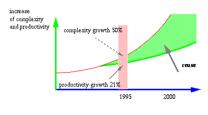
The rapid advances in semiconductor technology allows to build extremely complex ICs. At the same time the market pression requires the reduction of design time.
Even the most recent design tools are not sufficient to provide the requred design efficiency.
The solution is in the design reuse which is expected to be the prevalent method for the design of new systems on chip.
The design with reuse is closely related to the production of the ready-to-use blocks called Virtual Components or VCs.
In the future, complex ICs will contain several VCs assembled from the internal and external sources, mixed with some additional blocks designed specifically for the given IC.
For all this block to work together, it is necessary to use a common set of interfacing standards.
The essential task of VC modeling is the use of these standards to provide the reusability.
VHDL is only one of the standards required for this task.
The goal of the VSI standardization effort is:
"To specify or recommend a set of hardware and software interfaces, formats, and design practices for the creation of functional blocks that enable the efficient and accurate integration, verification, and testing of multiple blocks on a single piece of silicon "
VSI AllianceTM
The VC modeling is oriented towards the development of open specifications related to interfaces, data formwts and test methods allowing the integrators or "evolvers" to combine and evolve the intellectual property blocks.
The VC modeling is not related to the design of functional architectures, synhesis techniques nor fabrication processes.
The VC modeling concerns three kinds of audiences:
The providers should produce generic blocks with the interfaces following the VSI specifications.
The evolvers modify the current generation blocks into the next generation blocks. These modifications (adaptations) are requirement/constraint driven (e.g. the increase of the throughput). In principle, the evolutionary steps do not change the functional or even pin level characteristics of the modified blocks.
The integrators combine the provided end evolving blocks into the new generation systems.
Model of Complex Chip design flow
The following table illustrates the development stages of the design according to various disciplines or domains of design activity.
| design stage\design domain | system design
(VC integration) |
logic design
(VC development) |
test design
(VC development) |
physical design
(VC development) |
| system specification | algorithmic and
architecture design and partitioning |
target function
and performance |
test method
and test bench |
target power,
packaging and loading |
| detailed block and system | VC selection and
system simulation |
HDL development
and synthesis |
test structures,
vectors, ATPG |
floorplan,
estimated block size, loading |
| chip integration | block refinment
and interconnect |
test structure
insertion |
timing/size/
power/cluster |
|
| modification request | block modification
and verification |
scan chain
reordering |
post-layout updates
for timing/size/power |
|
| chip implementation | production test
creation |
silicon prototype
and certification |
VSI AllianceTM
Note: it is assumed that all new digital designs originate from an HDL description (VHDL,Verilog)
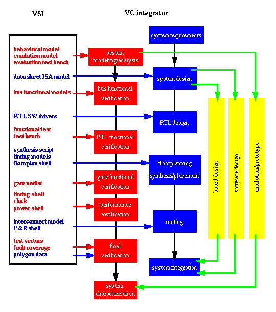
The next figure presents a view of the VC creation and integration process and their relationship to Virtual Socket Interface.
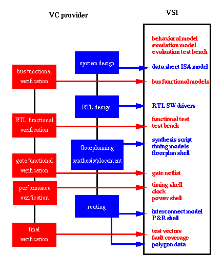
VSI AllianceTM
VSI AllianceTM
The methodology of the development and the evolution of VC is based on a set of concepts and terms. Most of them are provided already by VSI AllianceTM
Basic definitions
Virtual Socket InterfaceTM - a set of proposed standards and interfaces to enable on-chip system-level integration using pre-designed blocks. This approach enables component-based IC design
Virtual ComponentTM (VC) - a block that meets the Virtual Socket Interface Specification and is used as a component in the Virtual Socket design environment. Virtual Components can be of three forms: soft, firm, and hard.
Intellectual Property (IP) - the term "Intellectual Property" means products, technology, software, etc. that have been protected through patents, copyrights, trade secrets, etc.
VC creation - process by which a block is designed to a set of specifications. The outcome should be in a standard format with a pre-defined set of characteristics which will simplify the integration and verification.
VC evolution - process by which a new generation VC is developed from the current one. Basically, the ngVC should be compatible with its ancestor.
VC integration - process by which a designer combines and/or reuses multiple VCs to create a new much larger IC.
Hardness is the degree of the detail incorporated into the VC; it characterizes the development stage on the way from the functional specifications to a particular fabrication process.
The following table summarizes the essential differences between soft, firm and hard VCs.
| design flow | representation | libraries | technology | portability | |
| soft
not predictable highly flexible generic/configurable |
system design
RTL design |
behavioral
RTL |
IEEE std_logic_1164
IEEE numeric_std |
technology
independent |
unlimited |
| firm
predictable flexible |
floor planning synthesis
placement |
RTL & blocks
netlist |
refernece library
|
technology
generic |
library mapping |
| hard
very predictable not flexible |
routing verification | polygon data | process specific library & design rules
|
echnology fixed | process mapping |
One of the parameters characterizing the VC precision is timing representation. Soft VCs developed for the simulation purpose may provide only a crude timing based on the execution steps (for instance instruction cycle). More precise description may expressed with a clock precision. This precision is provided with the synthesizable soft VCs. Finally, a full timing precision (delay precision) is related to the hard VCs models.
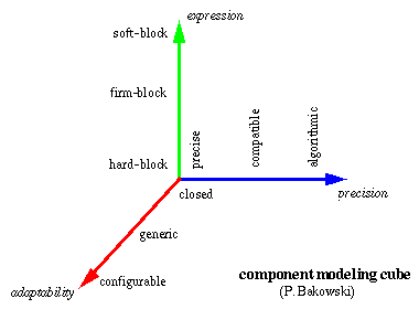
The VC modeling cube illustrates different kinds of VC models using three axes:
External links: